Equipment For Studying Centrifugal Force Manufacturer,Supplier and Exporter in India
Product Code : EL-TWL-11804
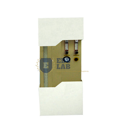
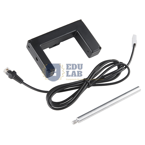
Quick Answer: Equipment For Studying Centrifugal Force uses a motor-driven 40 cm rail on which a low-friction truck slides outwards, its pull measured by a force sensor through a wire over a pulley. Rotation speed is read by a photogate sensor connected to a datalogger.
Last updated: October 2026
Key Features
40 cm rail with graduated scale, turned by a 24 V, 170 rpm geared motor.
Low-friction truck with weight holder, loaded with 10 g and 50 g weights.
Inextensible wire over a pulley at the rail end, connected to a force sensor.
Supports for the photogate and force sensors.
Polycarbonate protective guard.
Support base, 64 x 30 cm.
Technical Specifications
Specification
Value
Rail
40 cm, graduated
Motor
Geared, 24 V, 170 rpm
Weights
10 g, 50 g
Guard
Polycarbonate
Support base
64 x 30 cm
Sensors supported
Photogate, force sensor
About This Product
As the rail turns at variable speed, the truck is pushed towards the outer end and the wire passes the centrifugal force to the sensor. Students vary the truck mass, the angular velocity and the distance from the rotation centre to see how centrifugal force depends on each, and use the results to verify the familiar formula.
Frequently Asked Questions
Which relationships can be measured?
Centrifugal force against truck mass, against angular velocity and against radius from the rotation centre.
How is rotation speed measured?
A photogate sensor connected to the datalogger detects the rail's speed of rotation.