Frequency Modulation & Demodulation Manufacturer,Supplier and Exporter in India
Product Code : EL-EELE-11289
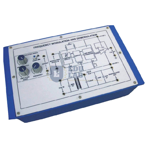
Quick Answer: The Frequency Modulation & Demodulation board has a built-in carrier generator, audio modulating signal, buffered FM circuit and demodulator, plus a variable DC input that shows the deviation in carrier frequency.
Last updated: October 2026
Key Features
Carrier generator circuit and audio frequency modulating signal on the board.
Frequency modulation circuit with a buffer stage at the output, and a demodulating circuit.
Variable DC source to show the frequency deviation of the carrier.
IC-regulated power supply of +/-12V DC at 100 mA.
Panel terminals and sockets for connections and waveform observation; stackable patch cords with 4mm spring-loaded plugs, half a metre long.
Mains on/off switch, fuse and jewel light; runs on 230V +/-10% at 50Hz.
Technical Specifications
Specification
Value
Power supply
+/-12V DC, 100 mA, IC regulated
Mains
230V +/-10%, 50Hz AC
Patch cords
4mm spring-loaded plugs, half metre, stackable
Circuits
Carrier generator, FM with buffer, demodulator
About This Product
Students feed the audio signal into the modulator, watch the carrier shift in frequency at the panel sockets, and recover the audio again in the demodulator. Detailed operating instructions accompany the board, setting out object, theory, design procedures, report suggestions and book references.
Frequently Asked Questions
How is frequency deviation shown on this board?
A variable DC source is provided so the deviation in carrier frequency can be seen as the DC level is changed.
What documentation comes with the Frequency Modulation & Demodulation board?
Detailed operating instructions giving the object, theory, design procedures, report suggestions and book references.